|
1
|
- DRAWDOWN = useable tank volume
- The amount of water that is stored in the tank between the pump cut-in
and cut-out pressures
|
|
2
|
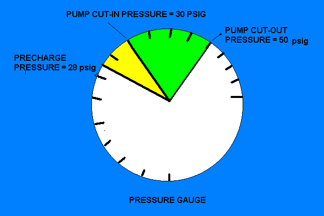
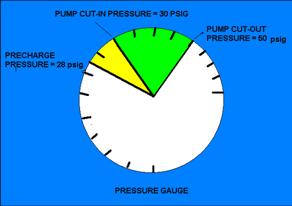
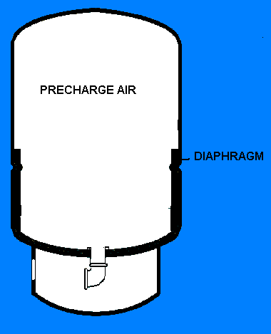
- PRECHARGE PRESSURE
- The gas pressure that is placed in the bladder tank at the
factory. Precharge pressure
should be 2 psi below the pump
cut-in pressure.
|
|
3
|
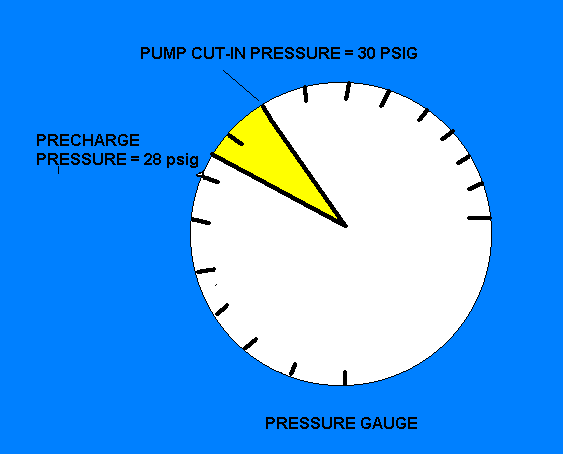
- PUMP CUT-IN PRESSURE - The pressure when the pump starts.
- PUMP CUT-OUT PRESSURE - The pressure when the pump shuts off.
|
|
4
|
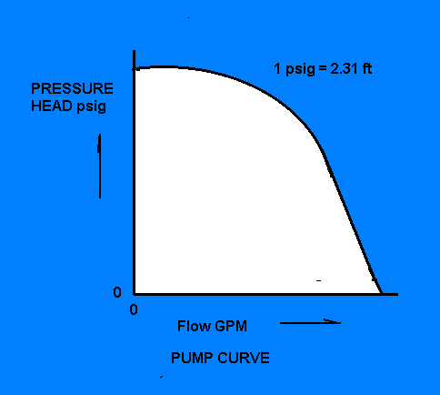
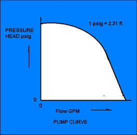
- PUMP CAPACITY
- The flow in gallons per minute(GPM) at a given pressure on the pump
curve.
|
|
5
|
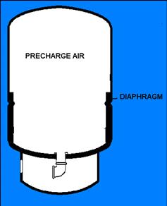
- Prior to the pump starting, the precharge pressure in the Well-X-trol is
checked. The precharge is 2 psig below the pump cut-in pressure.
|
|
6
|
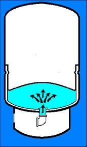
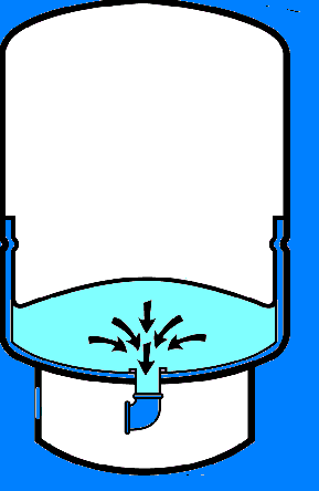
- When the pump is on and the pressure exceeds the precharge pressure, the
diaphragm will flex in an upward position, compressing the Well-X-trol
air and accepting the water.
|
|
7
|
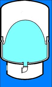
- When the pump cut-out pressure is reached, the pump shuts off. The water stored in the Well-X-trol is
under pressure and ready to be delivered to the system on demand.
|
|
8
|
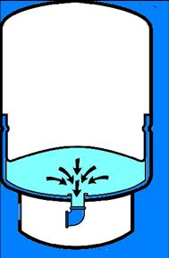
- When there is a demand and the pump is not running, water under pressure
will exit the Well-X-trol until the pump cut-in pressure is reached. The
pump will then start.
|
|
9
|
- What You Need to Know
- Pump capacity in GPM
- Minimum pump running time
- Pump cut-in pressure
- Pump cut-out pressure
|
|
10
|
- (1)Determine pump capacity by using the 7 minute peak demand and number
of fixtures ____ GPM
- (2)Determine the minimum pump running time in min.
- Up to and including ¾ hp………....1 minute
- 1 to 2 hp…………………………..2 minutes
- Greater than 2 hp…………………3 minutes
-
____ minutes
|
|
11
|
- (3)Determine the minimum system operating pressure (P1) at the
Well-X-trol location in psi.
This is the pump cut-in pressure.
- ____ psi
- (4)Determine the maximum system operating pressure (P2) (20 psi above
the pump cut-in pressure) at the Well-X-trol location in psi. This is
the pump cut-out pressure.
- ____ psi
|
|
12
|
- (5) Determine the Well-X-trol drawdown by multiplying (1) X (2)……………… ____
gallons
- (6) Determine acceptance factor using the pressures in (3) and (4) and
either the chart or the equation: AF = 1 – ( P1+14.7) ∕ (P2+14.7)
- AF = ____
|
|
13
|
- (7) Determine Well-X-trol Volume by dividing (5) by (6) ____ gallons
- (8) Select Well-X-trol model from the table.
- Model _______
precharged to ____ psi
|
|
14
|
- The following example will demonstrate the use of the eight steps in
determining the size and model Well-X-trol.
- Example: A 2½ bath home that requires a minimum system pressure of 30
psi at the Well-x-trol. The well
is capable of handling the system capacity demand.
|
|
15
|
- (1) Determine the pump capacity
- Using the Table for the 7 Minute Peak Demand, select the pump capacity
required. From the Table, the
flow is 14 gpm
- (2) Determine the minimum pump running time
- Assuming a 1 hp pump, the minimum running time is 2 minutes
|
|
16
|
|
|
17
|
- (3) Determine the minimum system pressure (P1) at the Well-X-trol
- This was given in the example as 30 psi
- (4) Determine the pump cut-out pressure (P2)
- This was given in the example as 50 psi
- (5) Determine the Well-X-trol drawdown
- Multiply Step 1 (14) X Step 2 (2) = 28 gals.
|
|
18
|
|
|
19
|
- (6)Determine the acceptance factor
- Using the Acceptance Factor table select the acceptance factor by
selecting the pump cut in pressure of 30 psi and vertically following
it down until it crosses the horizontal line of the 50 psi pump cut-out
pressure .31
|
|
20
|
- (7) Determine the Well-X-trol volume
- The volume is obtained by dividing the drawdown in step 5 (28 gals) by
the acceptance factor (.31) determined from step 6
- 28 gals /.31 = 90 gallons
|
|
21
|
- (8) Determine the Well-X-trol model
- Using the Well-X-trol Selection Table, pick a model that has both the
total tank volume and maximum acceptance equal to or greater than the
calculated value
- WX-302 precharged to 28 psig
|
|
22
|
|
|
23
|
- What You Need to Know
- Pump capacity in GPM
- Minimum pump running time
- Pump cut-in pressure
- Pump cut-out pressure
|
|
24
|
- Sizing Procedure Steps
- Determine pump capacity (gpm) from pump info
- Run time based on HP
- 1-2 hp ---------- 2 minutes
- ¾ or less hp --- 1 minute
- (gpm rating) × (run time) = drawdown
- (¾ hp 10 gpm) × (1 minute run time) = 10 gal drawdown
|
|
25
|
|
|
26
|
- The Well-x-trol’s precharge gas pressure is to be checked prior to
introducing water to the system.
- The Well-X-trol precharge gas pressure is to be 2 psi below the pump
cut-in pressure
- The pressure switch is to be located near the Well-X-trol
|
|
27
|
- A pressure relief valve is to be installed in the system with a relief
pressure equal to or less than the Well-X-trol design pressure. The flow capacity must be equal to or
greater than the pump capacity at the relief pressure setting
- The Well-X-trol is to be installed in line before a water softener or
other treatment
|
|
28
|
- Grit and rock flour
- Sulfate reducing bacteria (SRB)
- Iron related bacteria (IRB)
|
|
29
|
- John Nykamp, R.S.
- Environmental Health Program Specialist
- Guilford County Public Health Department
- 400 W. Market St
- Greensboro, N.C. 27401
- (336)641-4807 (336)641-7613
- FAX (336)641-3730
- jnykamp@co.guilford.nc.us
- Well Contractor Certification Commissioner
- http://www.ncwelldriller.org/
|

 Notes
Notes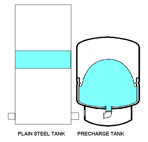