|
1
|
- Horsepower (HP)
- GPM rating
- Pump curves
- Voltage
- Wire sizing
|
|
2
|
- One horse power is the power to lift 33,000 pounds one foot in one
minute
- One HP is the power to lift 3962 gallons one foot in one minute
- One HP is the power to lift 10 gallons 396 feet in one minute
|
|
3
|
- 1 HP lifts 10 gallons 396 feet in one minute
- 50 PSI = 116 ft (115.5)
- 1 HP pump lifts 10 gallons 396 feet (280’ + 50 psi) in one minute
- Theoretically, a 1 HP pump provides 10 gpm @ 50 psi from a depth of 280’
|
|
4
|
- Theoretically, a 1 HP pump provides 10 gpm @ 50 psi from a depth of 280’
- Theoretically, a 1 HP pump provides 20 gpm @ 50 psi from a depth of 82’
- Theoretically, a 1 HP pump provides 5 gpm @ 50 psi from a depth of 676’
|
|
5
|
- Theoretically, a 1 HP pump provides 10 gpm @ 50 psi from a depth of 280’
- In reality, a 1 HP pump with a 10 gpm rating provides 4.6 gpm @ 50 psi
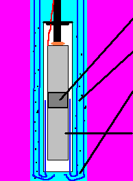
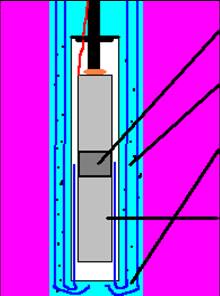
from a depth of 280’
- or
- 10 gpm @ 50 psi from a depth of 170’
|
|
6
|
|
|
7
|
|
|
8
|
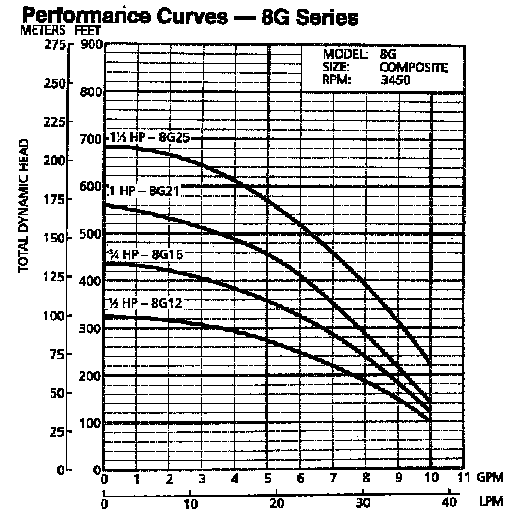
- TDH is lift + pressure(psi)
- GPM is delivery rate
- 8G is delivery rating
- Most efficient @ 7 gpm
- GPM / impellers
- HP is power rating
|
|
9
|
- Buy same pump as the pump in their neighbor’s well
- Replace old pump with same size even if going from a jet pump to a
submersible
- Don’t know how
- Takes a little time and effort
- Don’t understand the consequences
- Bigger pump costs more = more profit
|
|
10
|
- Up-thrust creates impeller-bearing wear
- Cavitation creates impeller wear
- Bigger is not always better
- Pump runs dry
- Thermal overload
- Customer is not happy!!!
- Installers may lose money and customers
|
|
11
|
- Avoid call-backs
- Save money on purchase price
- Save monthly on power consumption
- Avoid service calls and warranty problems
- Longer lasting pump when operating at the correct side of the curve
- Retain satisfied customers
- Word-of-mouth advertising
|
|
12
|
- Calculate the GPM required
- Measure and record
- Calculate you findings:
- TDH = L + F + P
- Choose correct pump from the “Family Curve” chart
- Typically, installers match the pump to well yield
|
|
13
|
- L = Total vertical Lift from pumping level in the well to the point of
delivery, in feet.
- F = Total of Friction losses, expressed as head in feet.
- P = Pounds pressure needed to operate the system, converted into feet of
head.
|
|
14
|
- A. Rule of Thumb:
- The “Rule of Thumb” is a simple method that can be used to determine the
consumption requirements of a water system. Simply count the fixtures
and water outlets in the home. This total number of fixtures should
equal the approximate GPM required.
|
|
15
|
- Kitchen Sink 1
- Dishwasher 1
- Bathrooms Sink 1
- Tub/Shower 1
- Toilet 1
- Laundry Washing Machine 1
- Utility Sink 1
- Outside Hydrants 3
- Total Fixtures and Outlets
10
|
|
16
|
- The Water Systems Council selected seven minutes as the peak period of
time because this is the average time of higher water usage for such
devices as a shower or automatic washer
|
|
17
|
- When – Most families have a peak demand for water early in the morning
when everyone first gets up or in the evening.
- How – Use Table 1 to determine the peak demand. Read down the column in
the table under the number of bathrooms in the house to the Normal seven
minute peak demand total.
|
|
18
|
|
|
19
|
- This is not an exact science!!!
- Obtain well yield and depth from driller
- If yield is 10 gpm or higher, use 10 gpm pump
- If yield is 3 gpm or less, use 5 gpm pump
- If yield is 3 - 10 gpm, use 7 gpm pump or 10 gpm pump, depending on depth
|
|
20
|
- Know your pump curve!
- Know depth of well and yield
- Can pump be placed 20’ off bottom and not over-pump well?
- If well is deep and has decent yield, can we go up in power and not
over-pump well?
|
|
21
|
- L = Total vertical Lift from pumping level in the well to the point of
delivery, in feet.
- F = Total of Friction losses, expressed as head in feet.
- P = Pounds pressure needed to operate the system, converted into feet of
head.
|
|
22
|
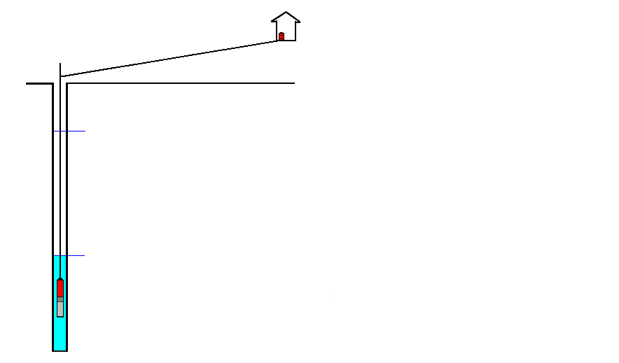
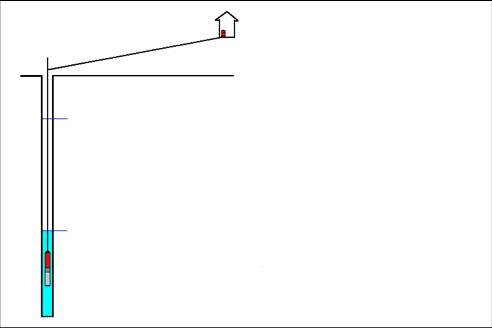
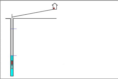
- 1st – Static Water Level
- 2nd – Draw Down
- 3rd – Pumping Lift (Static Level + Draw Down = Pumping Lift)
- 4th – Elevation Lift
|
|
23
|
|
|
24
|
- L = Total vertical Lift from pumping level in the well to the point of
delivery, in feet.
- F = Total of Friction losses, expressed as head in feet.
- P = Pounds pressure needed to operate the system, converted into feet of
head.
|
|
25
|
- To calculate the frictions loss multiply the horizontal run by the
friction loss per 100 then divide your findings by 100.
- 2. Multiply the drop pipe length by the friction loss, then divide that
answer by 100.
- Note: To find the friction loss per 100, go to your reference
book. Remember, to check the
friction loss, you will need to know:
- Pipe size
- Type of pipe that will be used
- The gallons-per-minute (GPM) required
|
|
26
|
|
|
27
|
- 5th – Pump Setting
- 6th – Length of Horizontal Run
- 7th – Fittings used to connect system
|
|
28
|
|
|
29
|
- To calculate the friction loss for the fittings to be used, look up the
number of equivalent feet of straight pipe in your reference book. Add these lengths together and
multiply by the friction loss, then divide by 100.
|
|
30
|
- Horizontal Run (60’ X friction loss 6.88 per 100’)/100 = 4.13’ or 5’
- Drop pipe length (180’ X friction loss 6.88 per 100’)/100 = 12.38’ or 13’
- 1”Fittings equivalent length in feet (29’ X friction loss 6.88 per
100’)/100 = 2’
- Total Friction Loss = 20’
- Note: Always round up fractions of feet when calculating friction loss.
|
|
31
|
- L = Total vertical Lift from pumping level in the well to the point of
delivery, in feet.
- F = Total of Friction losses, expressed as head in feet.
- P = Pounds pressure needed to operate the system, converted into feet of
head.
|
|
32
|
|
|
33
|
- Multiply the PSI (the average switch setting) by 2.31. This will convert service pressure to
feet.
- 50 psi × 2.31 = 115.5 or 116’
|
|
34
|
- L = Total vertical Lift from pumping level in the well to the point of
delivery, in feet.
- F = Total of Friction losses, expressed as head in feet.
- P = Pounds pressure needed to operate the system, converted into feet of
head.
|
|
35
|
|
|
36
|
|
|
37
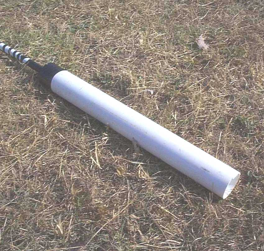
|
- Shroud is installed over submersible pump
- 4” wellseal is placed just above pump to hold 4” PVC casing
- Pump inlet is located mid-length of shroud
- Casing prevents pump intake from directly contacting sidewall of well
|
|
38
|
- Pump inlet is located mid-length of shroud
- Water flows past outside of shroud at high velocity
- High speed rock particles continue to fall
- Water flowing upward inside shroud cools motor
|
|
39
|
- Heat is the enemy
- Causes of heat
- Incorrect voltage
- Starting surge - cycling
- Poor water flow
- A cool motor lasts longer - it can run continuously
|
|
40
|
- In water up to 86º F, flow past motor should be at least .25 ft/sec
- .25 ft/sec past a 4” motor in a 6” well requires 13 gpm
- .25 ft/sec past a 4” motor in a 4” shroud requires 1.2 gpm
|
|
41
|
- John Nykamp, R.S.
- Environmental Health Program Specialist
- Guilford County Public Health Department
- 400 W. Market St
- Greensboro, N.C. 27401
- (336)641-4807 (336)641-7613
- FAX (336)641-3730
- jnykamp@co.guilford.nc.us
- Well Contractor Certification Commissioner
- http://www.ncwelldriller.org/
|

 Notes
Notes